Flying Blenders
Praj’s editorial note: This is an older project and the information on this page may be a little sparse. I like to leave these early pages up because there’s always a chance someone may find something useful in here and because I think every project, even a small or unfinished one, is an important part of my journey. After all, the tool works at both ends. Go ahead and scroll on through if you’d like, or check out some of the other projects for a better documented read.
I’ve always been interested in making things fly. As a little kid, I remember trying to make powered helicopters and planes by taping little brushed motors and propellors to cardboard paper towel tubes, filling it with AA batteries, and throwing the whole thing in the air hoping it would fly. Fortunately I’ve learned a little more about the world since then, so I was able to do a little better when I decided to get into more legitimate multi rotors.
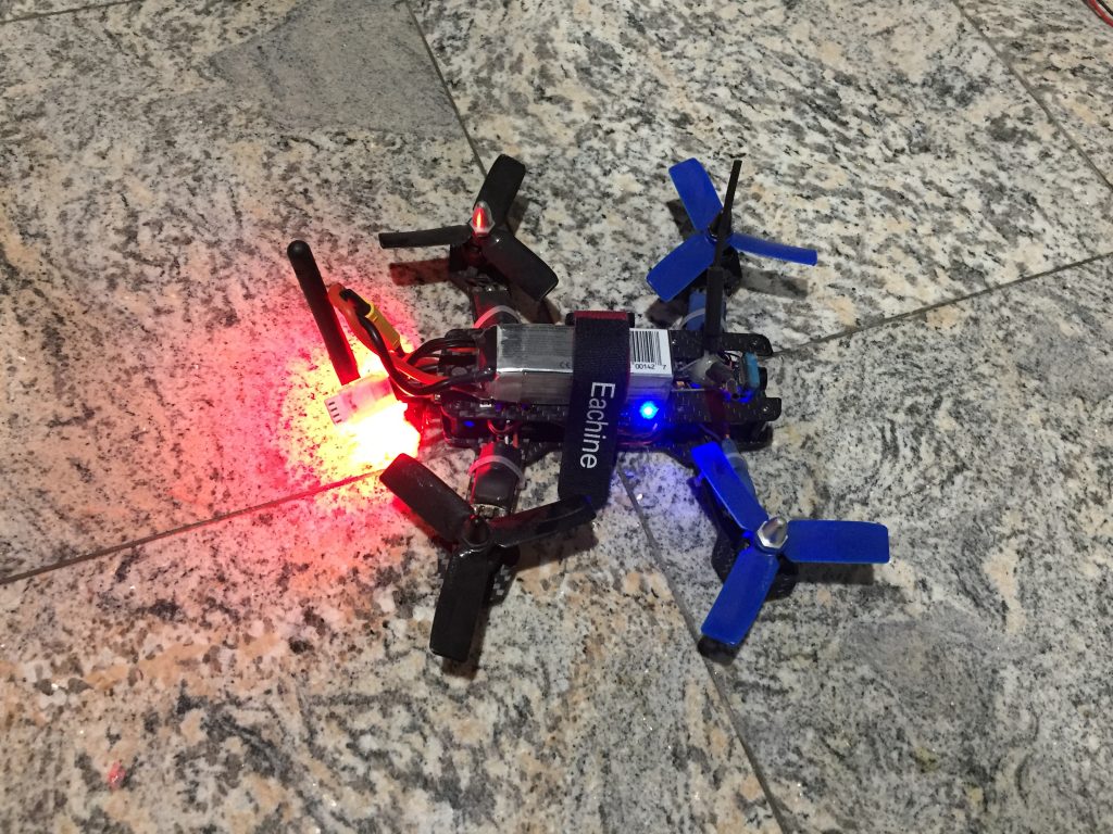
Mini Race Quad
When I build my first quadcopter, I didn’t really know much about what I was doing. I ordered a bunch of parts from Hobbyking.com that seemed like they should fit together, and figured I could fit it all together once they got here.
If I remember correctly, this little guy was a 160mm frame, with 3040 propellers powered with little 1306 BLDC motors and 10A ESCs (which turned out to be pretty under-powered). I used a KKmini as the flight controller, which worked OK out-of-the-box but I realized pretty quickly that it didn’t really have the necessary advanced features, customization, or speed that was needed for this kind of multi-rotor application.
I replaced it with an Omnibus F3 flight controller to which I flashed Betaflight. With this new controller and flight software, I had better control over radio inputs, craft behavior, auxiliary outputs, and even some spare DIO pins that I could use for craft telemetry. To take advantage of this, I added a HC-05 bluetooth module to transmit telemetry data to a mobile device (annoyingly, the HC-05 is not BLE compatible so only old android phones could be used to reieve this data). It also has a 200 mW 5.8 GHz video transmitter to send FPV footage back to my monitor or goggles.
V-tail Quad
The image below is a fairly standard setup for most of my homemade drones. A 2.4 GHz receiver (blue PCB) gets signals from the transmitter ) and sends the commands to the flight controller (black PCB in the center with lights), in my case, through the i-Bus protocol, which is a three wire interface based on the FrSky s-Bus protocol. The flight controller processes these instruction alongside its IMU readings, PID algorithms, and various flight behavior settings, before it sends a command to each of the 4 ESCs (not pictured- hiding under white base plate) to adjust the speed of the corresponding motor.
This particular flight controller is running the iNav firmware which provides features for GPS based drones. I’m used a uBlox GPS sensor mounted on top of the drone, and using this in conjugation with the IMU and barometer, the craft can maintain its position in 3D space with less than a few cm of deviation in any direction. That’s pretty good!
Most iterations of my drones also had an FPV camera and 5.8 GHz video transmitter with a RHCP antenna so that that I could see what the drone was doing in the sky (I’m a terrible line-of-sight pilot). In this particular drone, the flight controller also had a built-in OSD, that overlaid some information like PID settings, battery voltage levels, altitude readings, and an artificial horizon on the analog video feed. I’ve also connected an ESP8266 micro controller so that I can receive telemetry data and adjust some settings on the flight controller over WiFi on a mobile device.
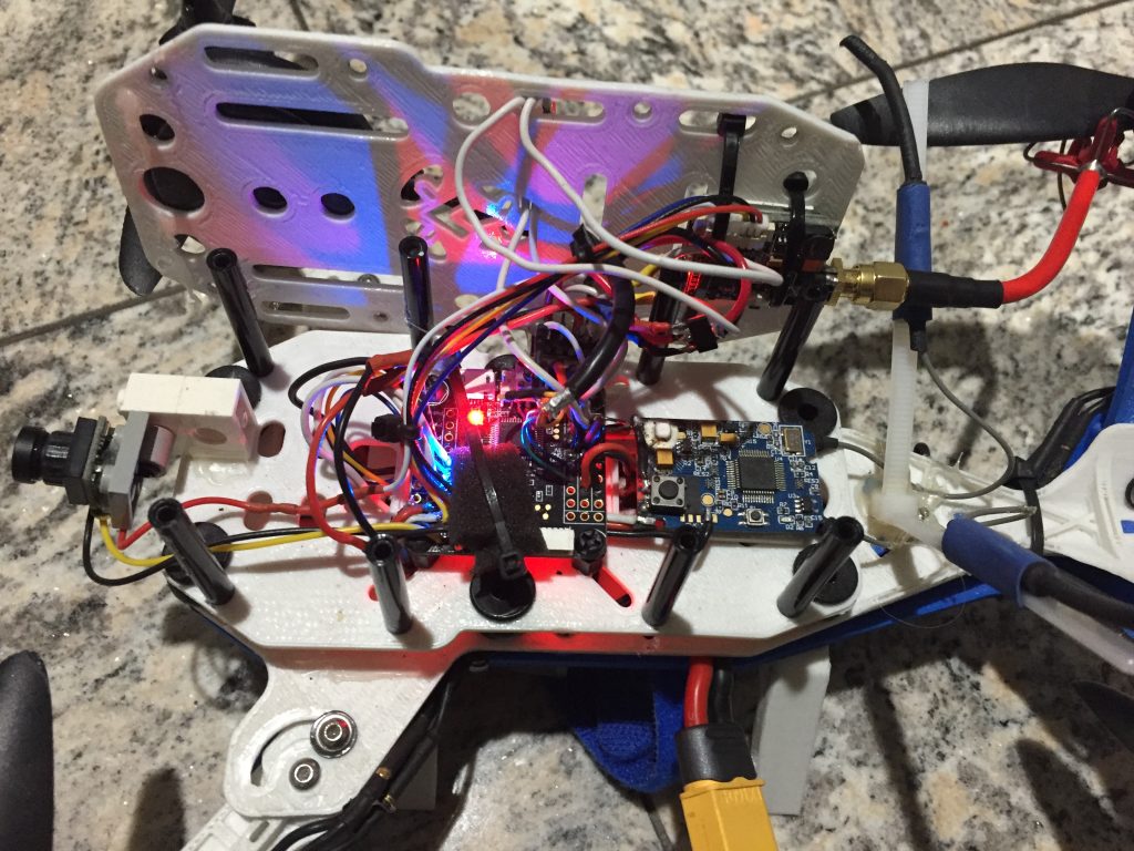
When building these drone, or really anything, I like to de-case and removed the pins from most of the components partly in order to save some space aboard the craft and partly because I really liked the look of the bare PCBs,
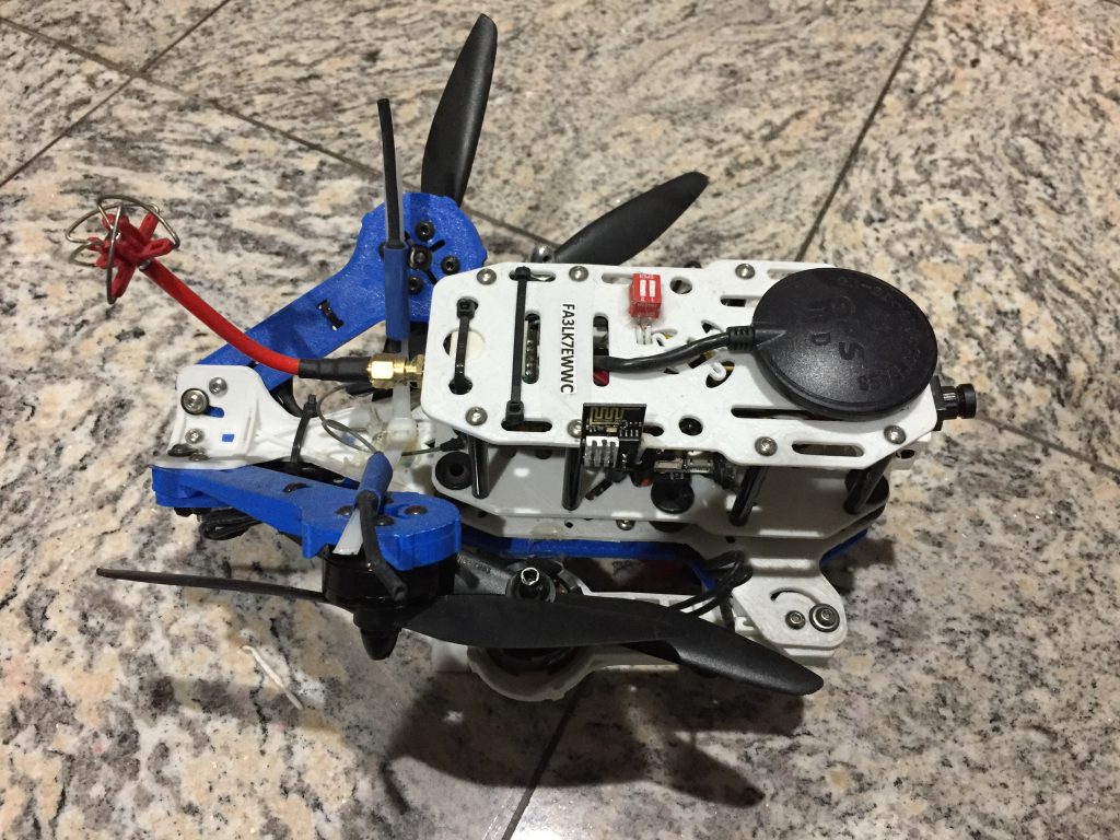
The guts above are a part of this GPS-based V-tail quad, so named for the V shape formed by the rear arms, which are tilted up at 45 degrees. This type of frame is actually kind of unstable and energy inefficient, and is certainly not suitable for autonomous navigation and aerial photography. Nevertheless, I chose it because I thought it looked really cool. It’s completely 3D printed in ABS and uses bigger 2204 size 2300KV motors with 6in props. The little DIP switch on top is used to switch UART serial control between the ESP8266 and the USB port on the flight controller
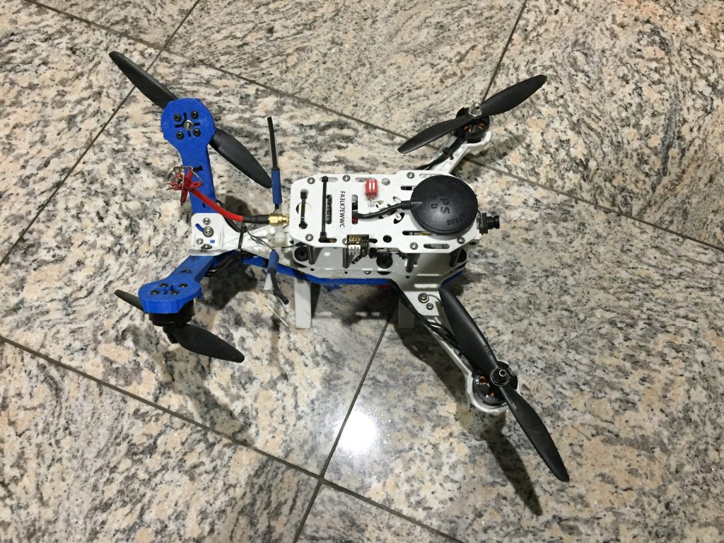
Plus it folds!
Tricopter
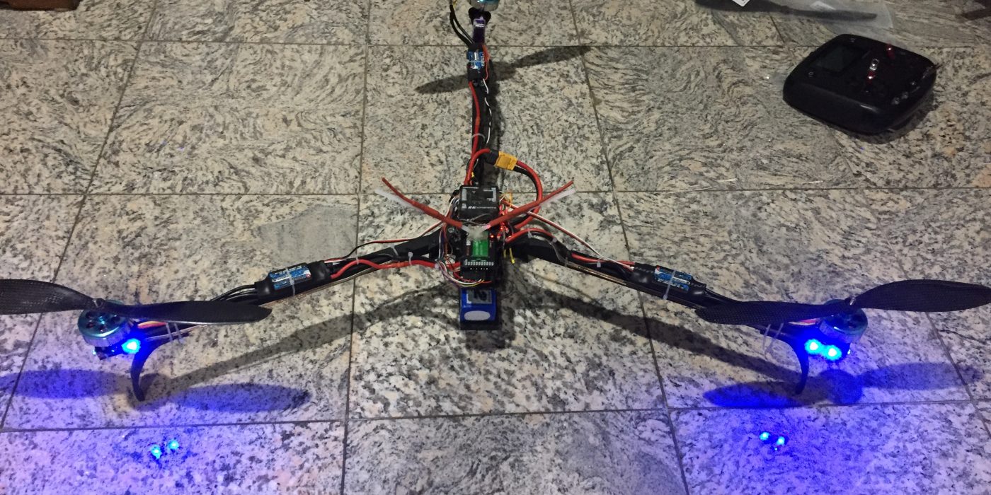
The most fun multirotor to build and fly was by far the tricopter. I went through several iterations and configurations with this one, since I kept finding new ways to improve the build. I had done a bit of research before building it and I decided to base the frame design on David Windestal’s tricopter. I built a small frame (roughly 8″ wingspan) using some square wooden dowels and MDF body pieces I had cut out on my homemade CNC router. This little tri was actually built before the v-tail quad above and it uses the same motors and ESCs.
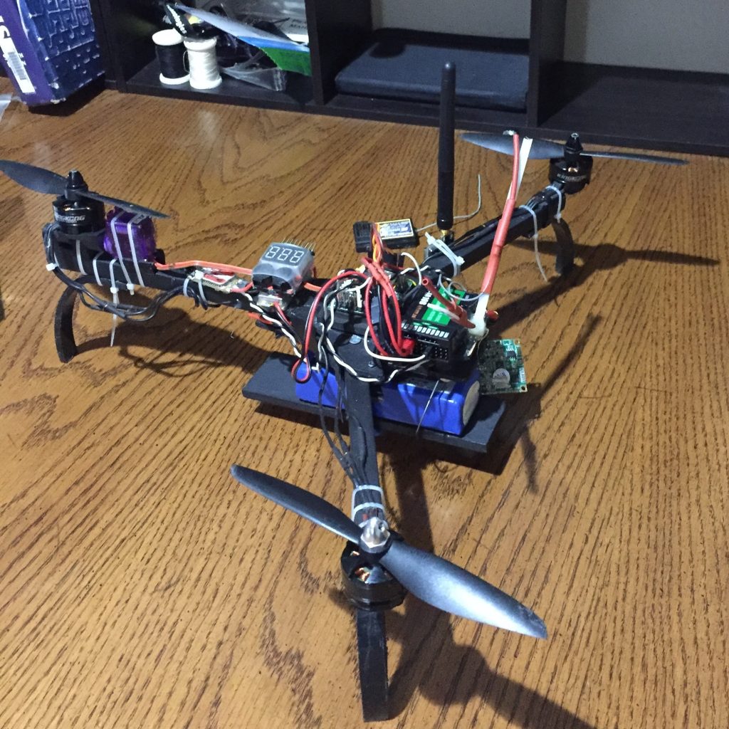
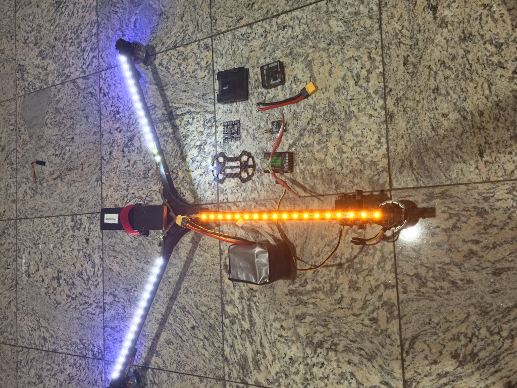
I got bored with this fast, twitchy thing pretty quick and decided to make it a little bigger. I rebuilt the tricopter using longer arms and upgraded to motors and ESCs that could spin huge 11″ propellers. With a wingspan of more than 26″ this large slow-flier was much more stable and energy efficient, making it perfect for use as an aerial video platform (though I never actually got around to that).
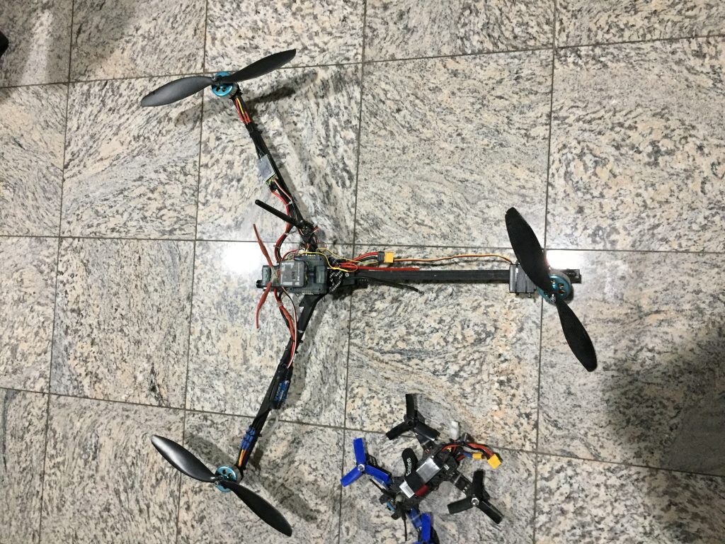
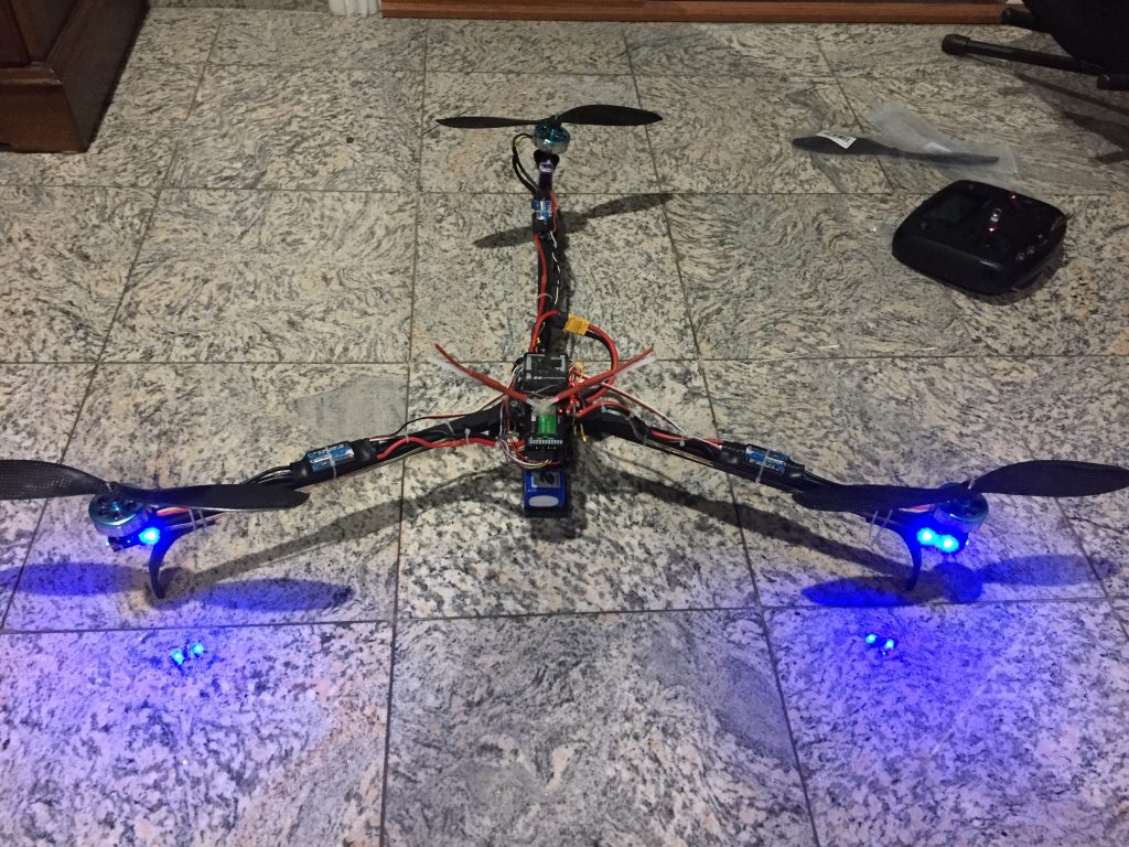
I rebuilt this one more time and added some LED strips to make it look a little cooler when it was in the air.
