Tesla Coil Part 2!
Praj’s editorial note: This is an older project and the information on this page may be a little sparse. I like to leave these early pages up because there’s always a chance someone may find something useful in here and because I think every project, even a small or unfinished one, is an important part of my journey. After all, the tool works at both ends. Go ahead and scroll on through if you’d like, or check out some of the other projects for a better documented read.
I had learned a thing or two from the thousands of mistakes I had made with the first SSTC, and this time I knew I needed to come up with a solid a plan before I got started building anything.
The tesla coil is a special type of transformer because it relies on the property of resonance in an inductor-capacitor circuit in order to develop the huge voltages. In the same way that you can push someone really high on a swing by providing a lot of small, carefully timed pushes, the primary coil of the tesla coil provides a lot of (relatively) small inductive pulses at the resonant frequency of the secondary coil to induce a very high voltage that breaks out as plasma arcs. We can do this because the seondary coil and its top load (the metal toroid on top) form a resonant LC circuit with reference to the ground. In a solid state tesla coil, this resonance is accomplished by adjusting the driving the primary coil using a feedback signal from the secondary coil. We start off pulsing the primary with a fixed frequency, essentially hitting the secondary coil like a bell, listening to it ‘ring’, and adjusting the frequency accordingly so we’re hitting this bell at the same frequency it is ringing at.
In this version, the Double Resonant SSTC, we take this technique of using resonance to exponentially grow the voltage in the secondary coil, and apply it to the primary coil as well. If we can also make the primary coil an LC oscillator, we can drive it at its resonant frequency to exponentially grow the primary coil current to levels much larger than the regular input voltage could produce, and subsequently generate even higher voltage on the secondary. The complication with this however, is that the resonant frequency of our secondary and primary coils must be matched, so my first step in this build was to get a sense of what my coil setup was going to be.
I used a really useful online calculator, JAVATC, where I was able to input parameters like secondary and primary coil size , room dimensions (since the size of the ground plane also affected resonant frequency), and get information back like the coupling coefficient, the size of the primary tank capacitance I needed to match resonance, and even an estimate of the amount of wire I would need.

With this tool, it was just a matter of tweaking parameters so that I could achieve my desired performance and size characteristics, and before I knew it, I had concrete plans to create my coil.
Winding the Coils
I decided on a smaller 2.5 in diameter secondary with over 1800 turns of 36AWG wire and 6 turns on the primary, which were wrapped around a piece of 6″ PVC tube. The top load was similar to the previous Tesla coil, and was made of 4″ diameter ducting wrapped into a 15″ circle. To make the turning of the secondary coil easier, I used a geared dc motor stuck on my bench PSU to spin the tube, and used a little micro-switch to coont the number of turns.
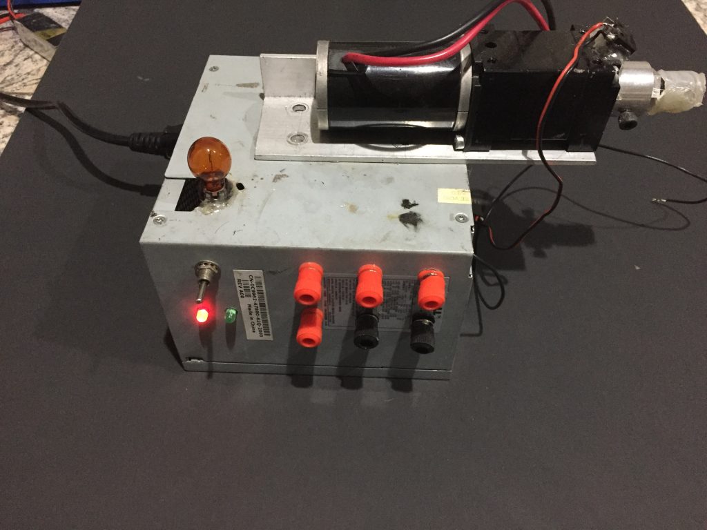
The 36AWG wire was incredibly difficult to handle. For one thing, it was about as thin as human hair but with a much lower tensile strength, which meant it would break if I even looked at it wrong. When I was winding the coil the first time, the wire actually broke in the middle of the coil. I did my best to solder it back together and continued with the fabrication of the coil, including laminating the whole thing with brush-on polyurethane.


Testing it with a slayer exciter circuit showed that it was arcing and shorting out at the splice point so I tried to go back in and fix it after-the fact.

At this point I had made too much of a mess so I started the whole process over and wound a new coil, making sure to be very careful about how much tension I was putting on the wire. I also ended up using magnet wire with a thicker insulation, which is why the final coil ended up being red rather than the orange in the pictures above.
I recommend reading Bigger Arcs with the DRSSTC for a more in-depth look into that whole process.
Driver Electronics
After finishing the coil, I turned my attention to the driving electronics. As I mentioned earlier, the electronics for the DRSSTC would be different from the electronics for the SSTC, most importantly because the primary coil needed to resonate. However, I also wanted this version to have more protection circuitry and better control over the interrupt signal, (musical or otherwise) since I was going to be operating this coil at significantly higher power levels.
For the main board, I settled on the UD 2.7, a circuit originally created by Steve Ward and optimized by Gao Guangyan from Loneoceans Labs. I won’t go into too much detail about how it works here since Guangyan (who apparently was also a student here at MIT) provides a great description on his page. This driver circuit had a lot of excellent features like over-current detection on the primary, multiple high-power gate drive outputs, and phase lead adjustment. I sent in the board files to a Chinese PCB manufacturer, and got a set of boards back that I populated according to the schematics. This was my first time with hand soldering SMD components so its not perfect, but I’m pretty happy with how it turned out.

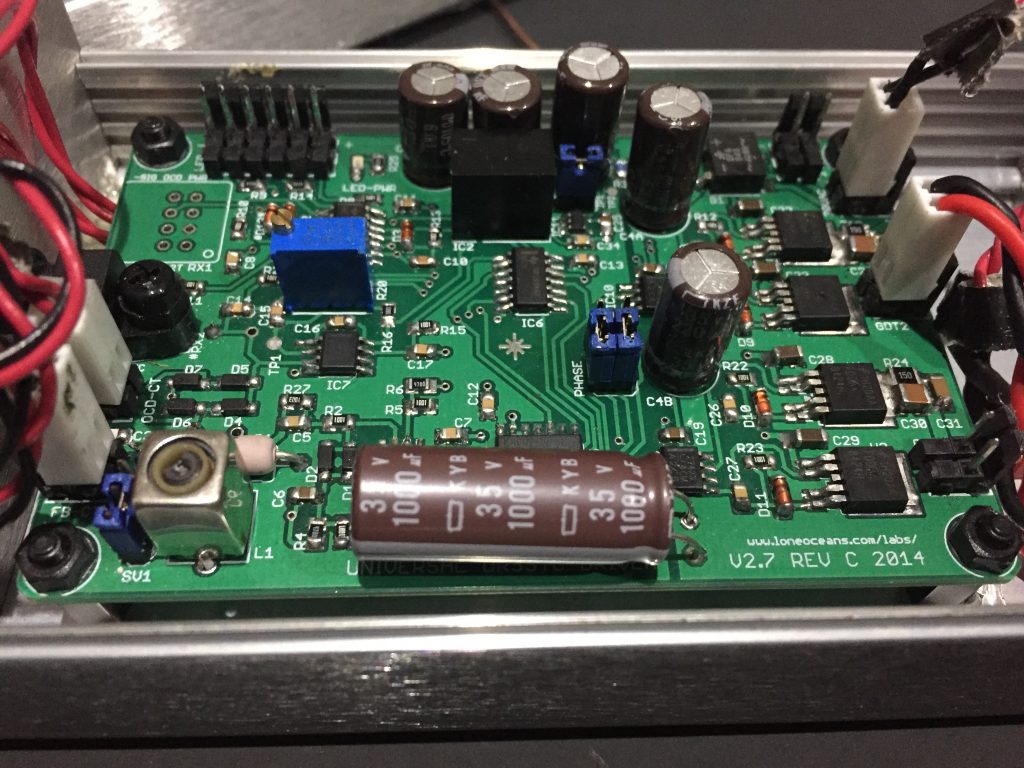
The over-current and feedback signals are each acquired through a set of cascaded current transformers (which is necessary because of the large currents flowing through the primary coil). I built the driver inside a grounded aluminum enclosure to protect it from accidental arc strikes and any other kind of interference.
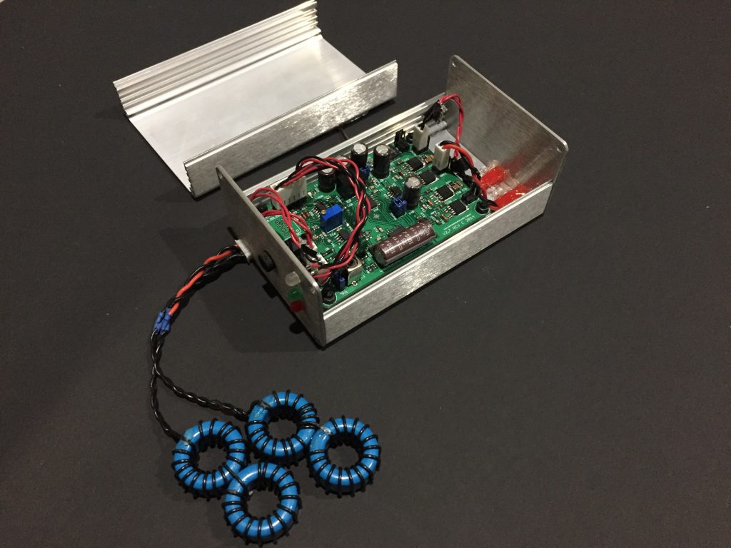
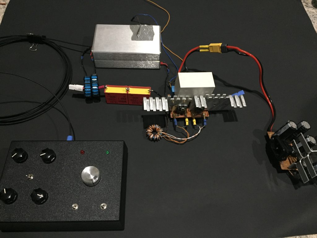
The actual current switching is done with high current transistors in a half bridge configuration. This time, I opted for the well-known FGA60N65 IGBTs, since IGBTs apparently tend to have lower losses in high pulsed-current application than MOSFETS. Since these IGBTs were going to be pushing hundreds of volts around (and hundreds of amps!), some protection electronics were necessary to prevent things like inductive spikes from blowing up the expensive transistors . Instead of driving the gates directly with the outputs of the driver, I wrapped a toroidal gate drive transformer (wire wrapped ring in bottom right), which allows me to isolate the driver board and the high voltage side while providing the same, high-current gate drive signal. In addition, I also added TVS diodes, zener diodes, and a comically large snubber capacitor (the big white box) to protect the IGBTs.
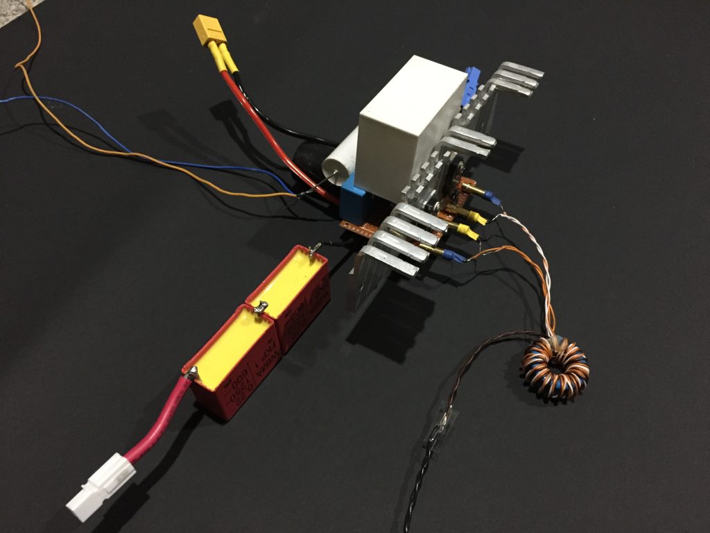
The above image also shows the tank capacitor for the primary coil. Its a MMC made up of two high quality WIMA MKP caps, whose series capacitance is equal to the value calculated in JAVATC (about 0.17 uF). When connected in series with the primary coil wundings, it creates an LC circuit that allows the primary coil to resonate at the same frequency as the secondary LC circuit.
Next up was the interrupter. Since the resonant coils can quickly ramp up to massive power levels, we can’t run the driver continuously. Instead, we turn it on and off at various frequencies and short duty cycles (on the order of tens of microseconds on-time), so that the coil is only ‘on’ for a very small portion of the time. Interestingly, by turning on and off the tesla coil arc at a given frequency, we are also heating and cooling the air around the arc as it materializes and disappears. This produces pressure waves, at the frequency of modulation, that we hear as sound! To provide this signal, we have a user controllable interrupter, which sends a square wave to the driver telling it when it should be on and off. Mine consisted of a couple of 555 timers, along with a 3.5mm audio jack and an op-amp circuit so that I could use music as the interrupt signal and hear it through the arc. Because of the nature of this circuit, I could only play songs one note at a time (i.e. no polyphony) so preparing sounds for the coil was a pretty tedious task of downloading MIDI files, editing them to remove any polyphony, and resynthesizing it using only short-duty cycle square waves.
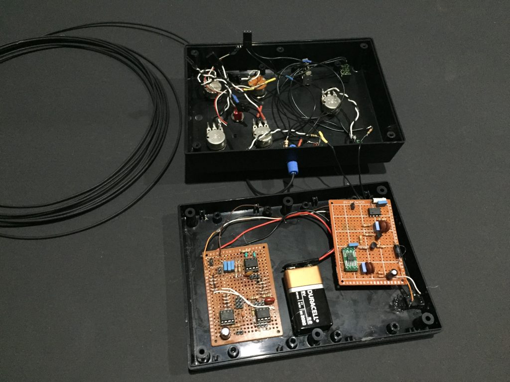
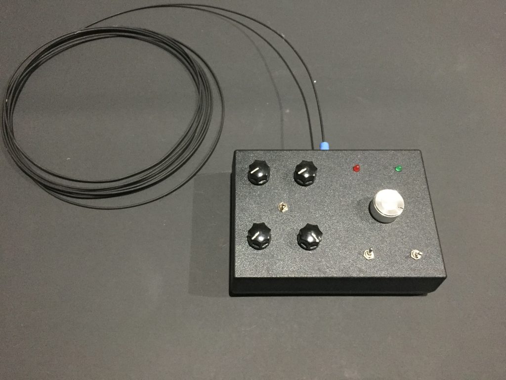
This is the interrupter all closed up. I have several potentiometer knobs in front that let me adjust duty cycle and frequency in continuous mode, burst mode, and audio mode and switches to let me toggle between the modes (and for an extra challenge, nothing is labled!). LED lights are used as indicators so I can keep track of the interrupter output. The output of the interrupter is transmitted to the driver board via a fiber optic cable. This is used instead of wires in order to prevent any high voltage from the arcs being conducted back to the user (me!). I’m using a cheap 660nm emitter and receiver and simplex polyethylene fiber since signal attenuation is not really a concern.
This is the full assembly of the driver circuitry, not yet connected to the primary coil. At the bottom right is a bridge rectifier that converts the 120 VAC from the wall to around 170 VDC to be fed into the half bridge.
Finishing Up
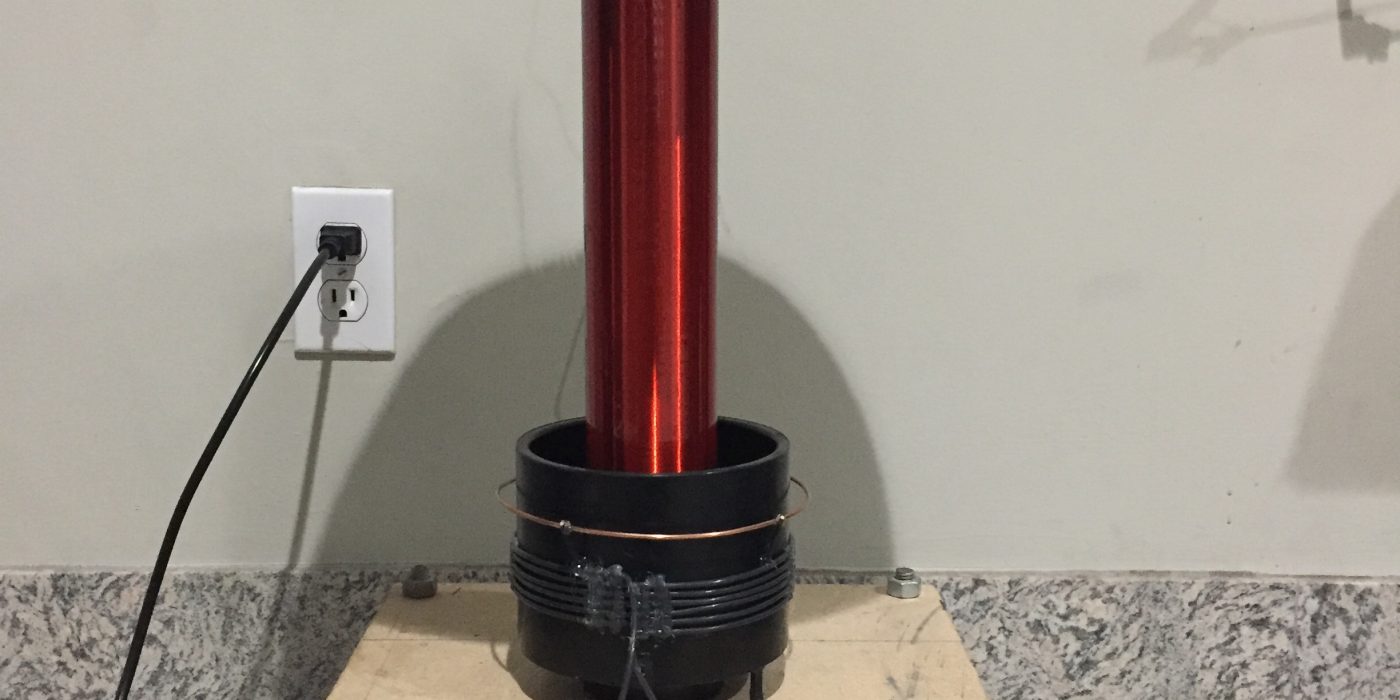
Now that I had the electronics together, I had to make some adjustments like phase lead and over current using a dummy-load (a big hunk of steel) in place of the secondary coil. In addition, I had to tune the gate drive transformer (GDT) for a clean,optimal gate drive signal with no ringing, all of which was really hard to do without a real oscilloscope( In fact I don’t recommend anyone try building something like this without access to an oscilloscope!) After assembling all the coil components,this is what it looked like. I added a copper strike ring to prevent any accidental arcing to the primary, which would immediately destroy the electronics.
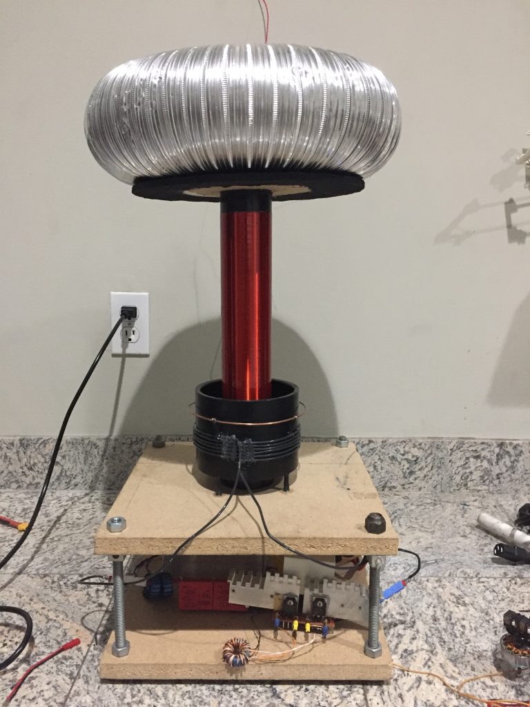
To run the coil, one side of the secondary coil must be connected to the top load, and one side should be connected to earth ground. Although the ground pin in a household outlet does indeed connect to earth ground, to prevent any damage to other electronics in my house, I didn’t ground the coil through the outlet. Instead, I ran a wire outside and tied it to a long metal rod, which I hammered into the damp ground.
The video below shows the coil producing arcs, playing various songs, and lighting up a little florescent lamp tube.
If you’re looking at that and thinking “Hey, that’s kinda underwhelming”, well I’m right there with you. This coil was certainly capable of producing bigger, more impressive arcs, but it needed some serious tuning to get there.
UPDATE: Check out my page Bigger Arcs with the DRSSTC where I do just that (quite successfully, I might add) and reattempt the same songs with the updated configuration!


who sells cbd oilpipes