Flipping the bird
It’s secret santa time and I’ve decided to make a little brass knife.

Things on This Page
Design
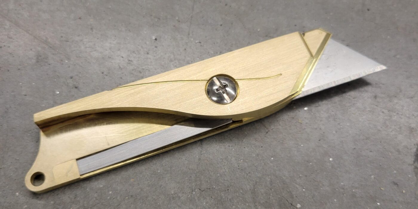
This is a folding knife, and it holds a standard utility knife blade. The person receiving this enjoys birdwatching as a hobby, and so I designed it to look kind of like a bird when folded out.

Specifically this is a liner-lock folding knife. As the name suggests, this type of configuration has a spring bar of some sort that lines the inside of the frame. When the knife is folded out, this liner pops out and prevents the knife from collapsing during use. When needed, the liner can be pushed out of the way and the knife refolded. In this knife, the liner is the gray bar spanning the bottom of the knife in the above image.
These are the components I will need to make

Almost every component of this knife will be made out of 1/8″ 385 brass bar stock except the liner, which will be cut from spring-temper stainless steel sheet.
The knife is designed to carry a single utility knife blade. I chose this option for ease of replacement and because I didn’t have the time or resources (yet) to make a blade from scratch.
The pivot around which the knife folds is a 1/4″ diameter binding barrel and screw. This allows the knife to be easily disassembled when it’s time to switch out blades.
Machining
The blade holder was arguably the most complex part, and I decided to work on that first.
The back side of the holder is where the blade is installed. It features a small recess that matches the blades thickness and most of its profile. This profile is only very slightly larger than the blade, so as to create a transitional fit. The goal is to be able to press in or remove a blade by hand, and have the friction keep it in place.

Circular relief cuts are added at every sharp corner so the blade will fit after machining.

This recess and the pivot hole will be machined first. I set up the CAM so that the bulk of the machining is done with a 1/16″ flat endmill, and a 1/32″ flat endmill is used to cut out the corner reliefs.

The front side of the blade is a simple 2D profile with a 3D taper along the edge

I used a 1/32″ ball endmill to create the taper and a 1/16″ flat endmill to cut out the profile of the part and separate it from the parent material.

Because the parts were rather small, I did all the machining on an Othermill, which I had thus far only used for PCBs. I indexed the material by aligning it with the sides of this sacrificial plate and stuck it down with double sided tape.

A piece of copper tape creates an electrical path between the bed and the material (the double sided tape is not conductive) and helps the machine pick up the height of the material. Once, the material is placed and the CAM is loaded, we’re off to the races.

Here is the blade holder part after going through the two machining setups. The factory finish is still present where the brass wasn’t machined, but I’ll address that at a later step.

I was expecting to have to remake this part a couple times to get the blate to fit just right, but it ended up perfect on the first try. It took some force to get the blade in, but it could be done by hand. Once it was in there, there was no way it was falling out on its own.


There was a tiny amount of misalignment and this edge of the stock was not fully machined. I’m not too worried about this, once I get through with sanding, it will be impossible to notice.

My stepover was quite coarse and I got these lines along the taper. This was a happy accident and I actually really liked the look of these, so I didn’t bother trying to sand them down or remake the part.

The CAM and machining of the other brass parts was done in much the same way.

To make the stainless steel liner, I printed the shape out on paper, glued it to the piece of sheet meatal, and used a combination of a floor sheer and a disk sander to bring it to shape.

I left it intentionally long, so that the length can be adjusted once the rest of the components were in place. It will be bent and sized before installing it there permanently.

Soldering
With all the parts made, it was time to start soldering the three pieces that make up the frame of the knife. A big reason I chose brass for this project was because it would be easy to jjoin with the soldering tools I had on hand. It would have been much more challenging to create the required geometry from a single block of material.
I clamped the pieces together and used some slips of paper as shims for the folding portion. This to prevent the frame from being soldered too tightly and preventing any motion whatsoever. These paper shims ensure there is just enough space for the knife to fold back and forth without binding up.
I used the shank of a drill bit to keep all the parts concentric while soldering. It’s not critical that all the pieces are perfectly placed, since I would be drilling and reaming the pivot hole later anyway. Any small misalignment now would be eliminated at that step.

Here is the frame after soldering and wiping away the excess. The pieces are bonded very strongly together.

Looking through the bottom we can see hints of the solder on the edges of the central piece. This indicates the solder was able to wick in and coat the entire joint area.

A little bit of cleanup with sandpaper gets rid of the solder residues and patina on the outside of the brass. I sanded all the way up to 1000 grit and than did a few unidirectional swipes on 800 grit paper to give it this brushed finish.


Fine Tuning
I placed the blade holder piece back into the frame and used the largest guage pin I could fit in all three holes to hold the parts together. With this pin in place and everything as concentric as it was going to get, I applied a generous amount of hot glue to temporarily fix the parts in place.

Now I could remove the guage pin, and use reamers of increasing diameter to bring this hole to size. Between each reamer, I checked the fit with the binding barrel. I wanted a very close sliding fit inside this hole—even a little too big would manifest as slop in the folding movement of the knife.

Installing Liner
With the pivot in place, it was finally time to cut and install the stainless steel liner. This had to be just the right length so that the blade holder could get past it in its fully open position but not be able to wiggle once it’s there.
After trimming this down to size, I used a little bit of solder part to install this brass cover and trap the liner in place permanently

The solder paste was reflowed using my little miniware hotplate, which I normally use for PCBs.

A little bit of sanding helps to level the retainer piece and blend it in with the rest of the knife frame.

Here is the mechanism in action. While the knife is not fully open, the liner spring sits below the holder. The liner, which acts as a preloaded spring, presses against the surface of the blade holder but can’t get past. The holder can swing freely.

Once the blade holder is pushed to it’s full open state, the liner can escape from behind the liner and spring up. Now with the liner in the way, the blade holder can’t return. It is mechanically stuck in this fully open state until the user resets the mechanism by pushing the liner down and singing the blade holder back on top of it to close the knife.

Complete
The following videos show the folding and locking mechanism in action. Even though the liner looks flimsy, it locks the knife in place very rigidly.


Packaged and ready to go!


